Tips on part and assembly modeling
日期:2023-11-30 09:47:07 發布者: 瀏覽次數:次
Design takes a lot of effort and can be time-consuming. In this article, we will introduce some tips that can speed up your part modeling and assembly process. Hope that these can benefit your work.
Scenario 1:
We are creating parts and would like to model faster.
Like using Windows Explorer, we can use “CTRL+ Drag” to make copy of items in SolidWorks:
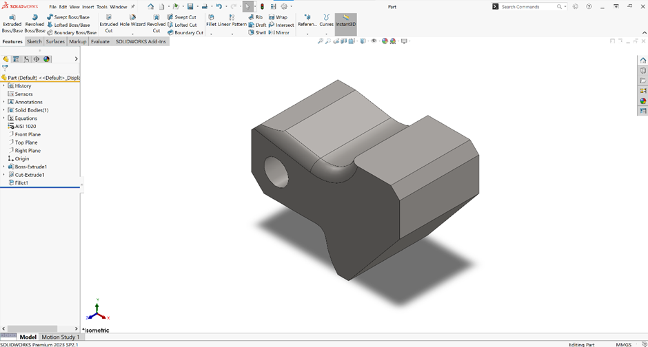
A fillet feature has been applied to the model.
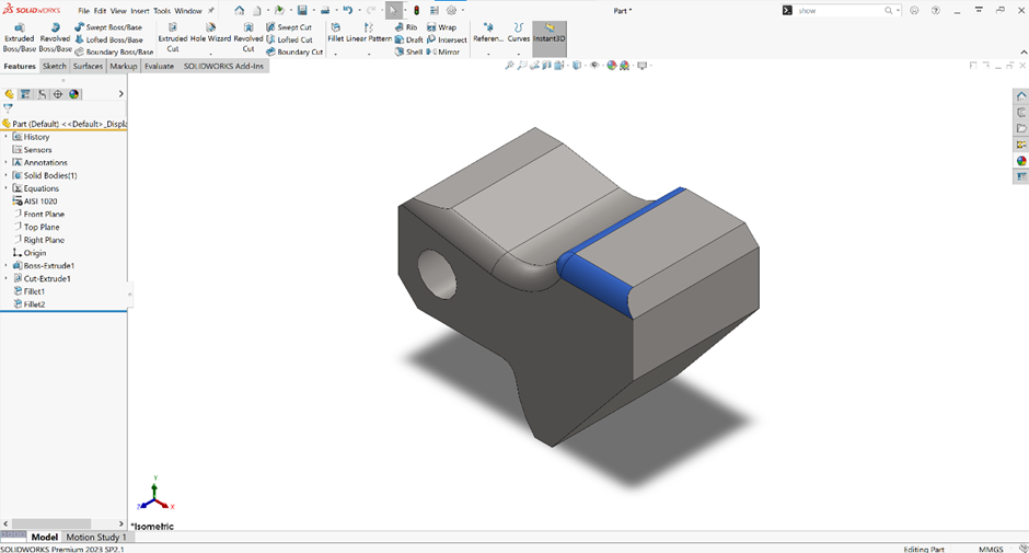
We can use CTRL and hold the left click mouse key to drag to copy fillets/chamfers to another place.
Planes can be essential to our modeling. We can also qui ckly create planes using the same shortcut commands. This is applicable in both Assembly and Part modeling:
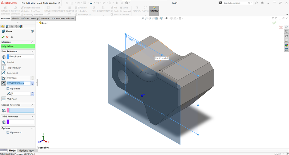
A copy of plane (parallel to the selected plane) can also be made by clicking CTRL and dragging left mouse key.
Scenario 2:
We reorder the feature in the FeatureManager Design Tree so that we can have more flexibility in our design process. However, the system does not allow us to do so.
This is because our feature has dependency/dependencies on the parent feature(s). In this case, we can use the Dynamic Reference Visualization to view its parent/child features. It is used to display the parent and child dependencies by hovering over that feature in the FeatureManager Design Tree.
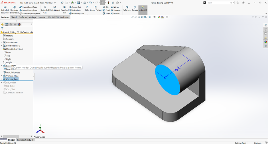
We want to drag the feature to reorder it in the FeatureManager Design Tree, but the system says “Cannot reorder. Change would put child feature above its parent feature”.
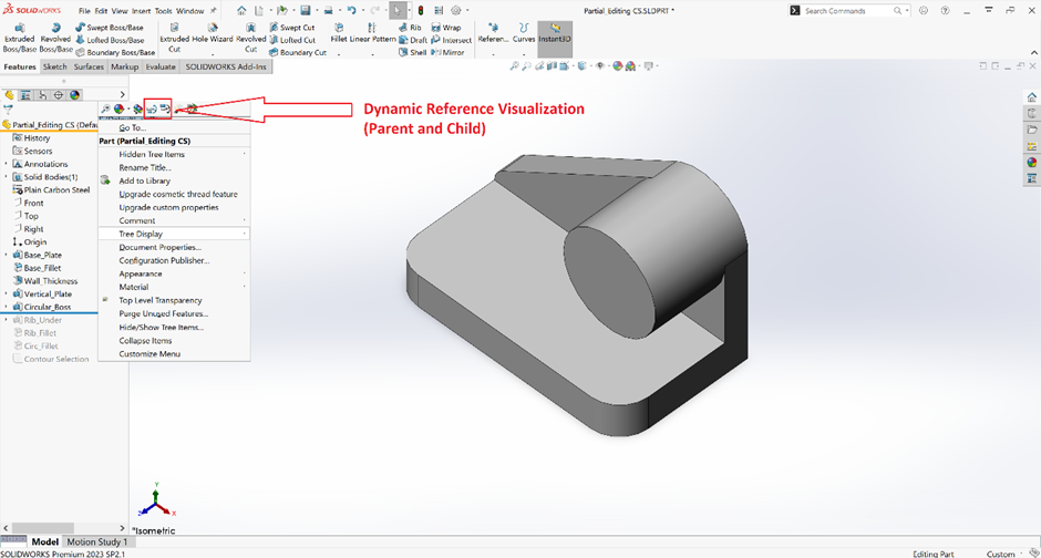
We can right-click the model in the FeatureManager Design Tree and turn on the Dynamic Reference Visualization (Parent and Child).
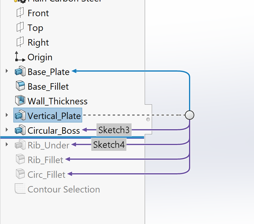
After that, we can hover the feature to view its parent and child feature(s). Blue arrows represent the feature’s parent dependencies, while the purple arrows represent the its child dependencies.
We have prepared some assembly shortcuts and organization tips to you as well.
Scenario 3:
We have many components in our assembly in the project. Therefore, we are going to add a lot of mates to assemble them.
SolidWorks has smart mate command that helps us to mate our components faster. We can use “Alt + Drag” to mate the components/sub-assembly. Mates including concentric mate and coincident mate are supported:
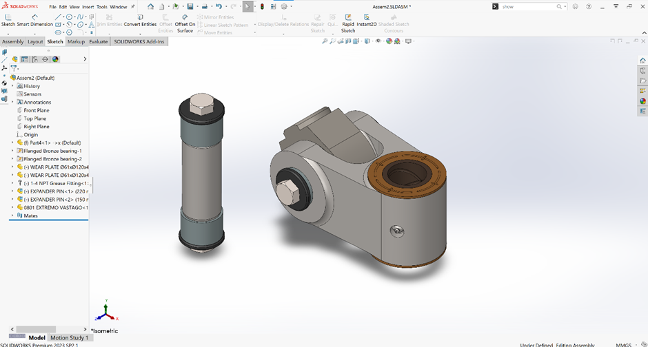
We have a sub-assembly that is ready to be mated to the main part.
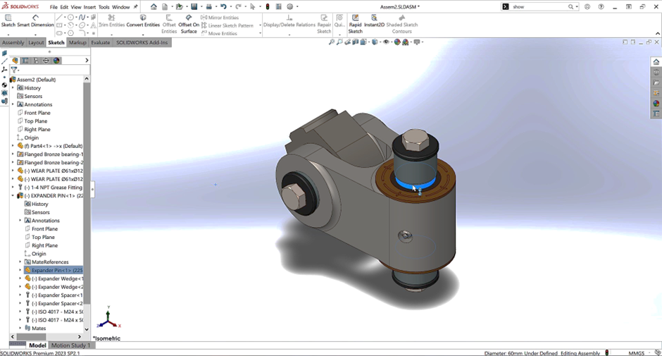
We can use “Alt + Left Mouse Drag” to drag the item to a cylindrical face. The mouse cursor symbol will change when we are applying it right. This applies a concentric mate to the main assembly and sub-assembly.
Scenario 4:
We have certain amounts of components in the assembly and we would like to hide some of them:
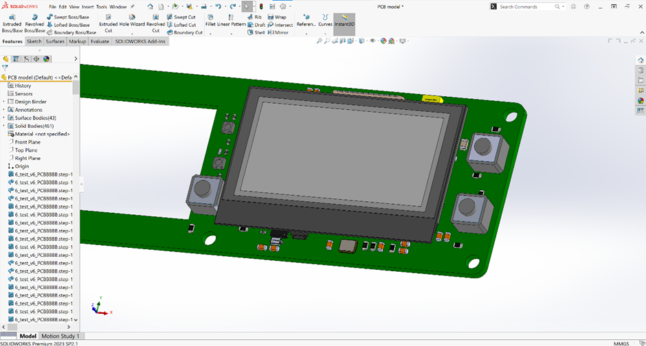
We have certain amounts of components in the assembly.
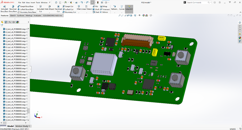
Apart from right-clicking the model in the graphics area or FeatureManager Design Tree to hide it, we can also hover the cursor to the OLED model and press “Tab” to do so; we can press “Shift + Tab” to unhide it.
Scenario 5:
We have certain amount of components in the assembly which includes different modules. It has been difficult for us to organize them.
We can add folders to the assembly’s components so that we can have a better organization of the files:
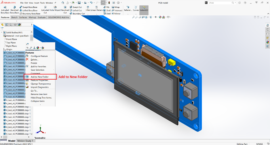
We can select the items in the FeatureManager Design Tree and right-click them to select “Add to New Folder”.
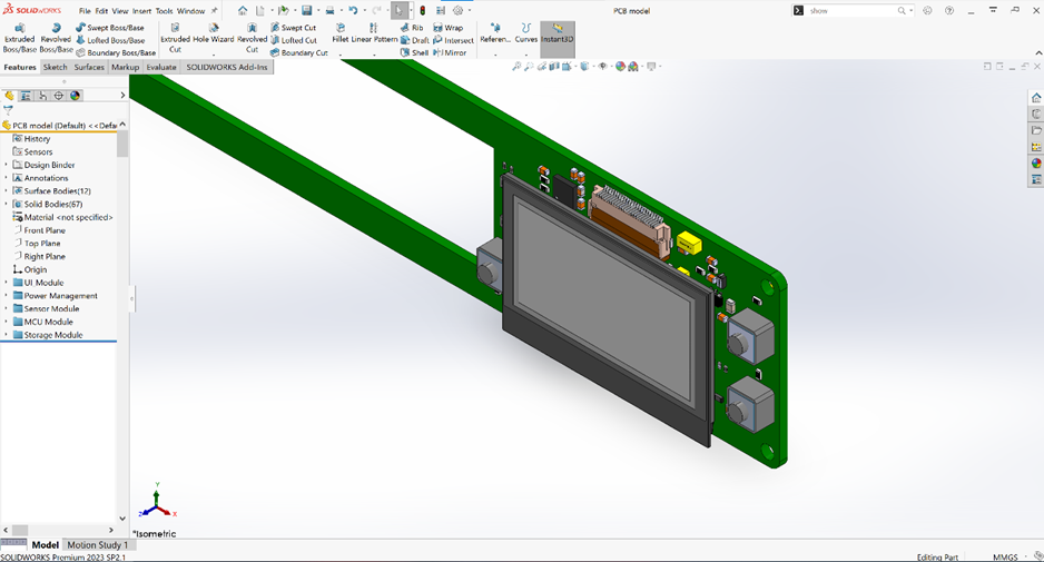
We can then have a better folder structure in the assembly.
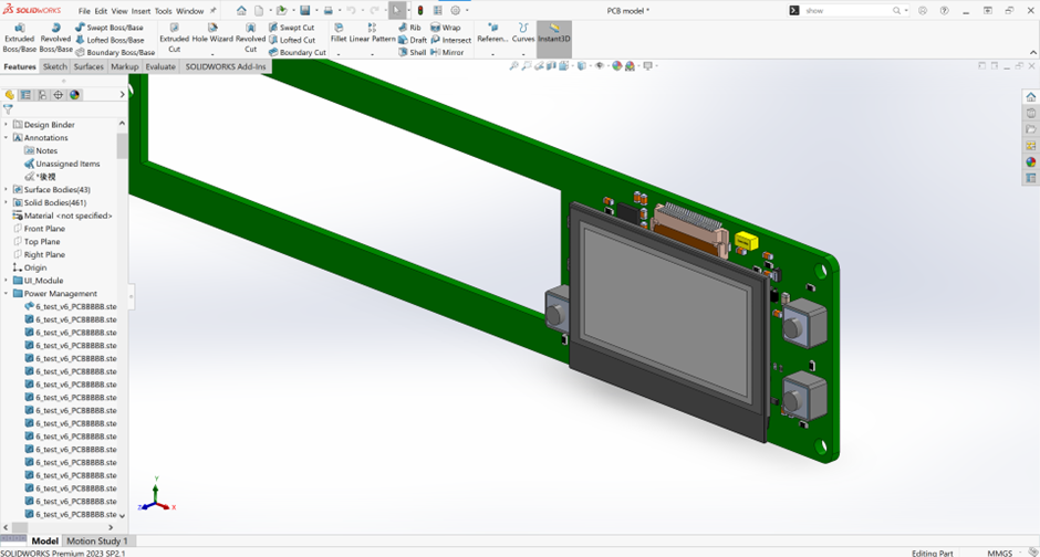
Often, we expand folders in the FeatureManager Design Tree and it gets messy.

We can use “Shift + C” to collapse all the folders. This is also appliable in Part modeling and Drawing.
Note: We can create sub-folders in Solid Bodies and Surface Bodies folders as well.