SolidWorks | How to create your own drawing template?
日期:2023-07-20 15:10:49 發布者: 瀏覽次數:次
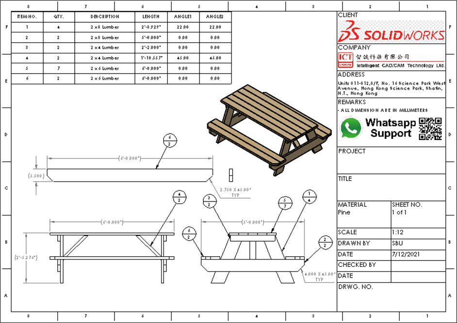
Creating a drawing template can be useful for organizing and standardizing 2D drawing data. A well-designed template ensures consistency, accuracy, and efficiency when inputting information just like spreadsheet. In this blog, we will outline the step-by-step process of creating a sheet template in SolidWorks. Below is a preview of the result.
Let us start to build.
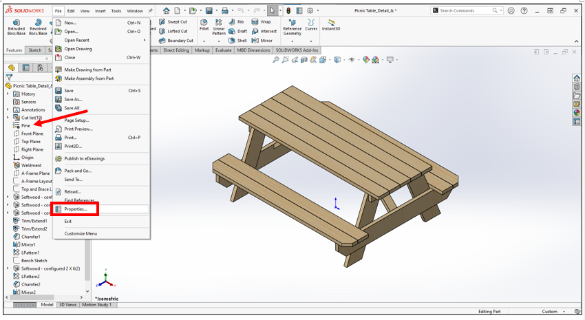 1. Open a part file which has material defined, then open the “Properties”.
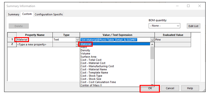
2. Type the “Property Name” as “Material”, then select “Material” at “Value / Text Expression” and click “OK”. (Optional: you can add another custom property to the drawing template.)
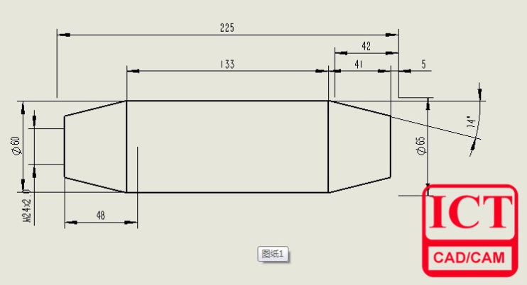
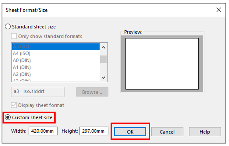 3. We will apply an A3 size (420mm x 297mm) as an example.
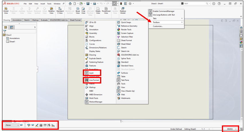
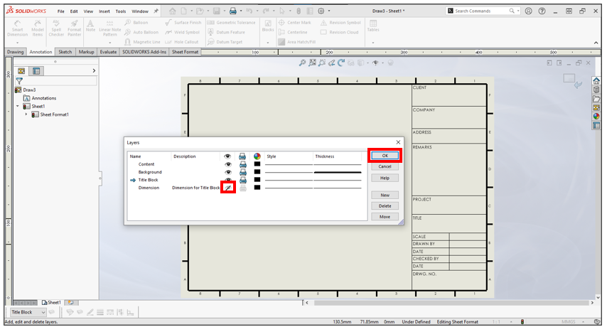
4. Right-click the “Command Manager” > “Toolbars”, show “Layer” and “Line Format”. The “Layer” and “Line Format” will then be showed at the lower left corner.
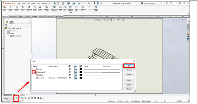
5. Click the “Layer Properties”. Add four layers showed above and double-click the “Background” to set it as a current layer. The “Thickness” of “Background” is set as 0.5mm. Click “OK”. We can control the setting of the layers individually like Show/Hide, Colour or Thickness.
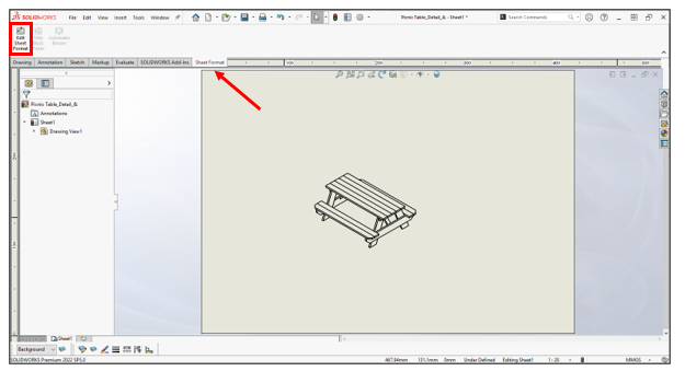
6. Click the “Edit Sheet Format” at “Sheet Format” tab.
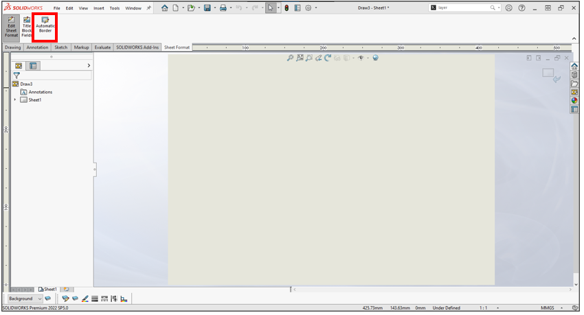
7. Click the “Automatic Border”.
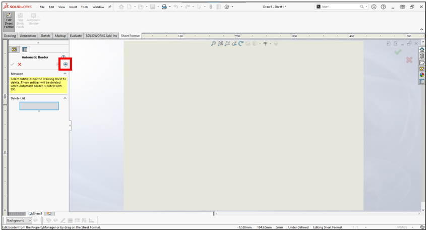
8. Click “Next”.
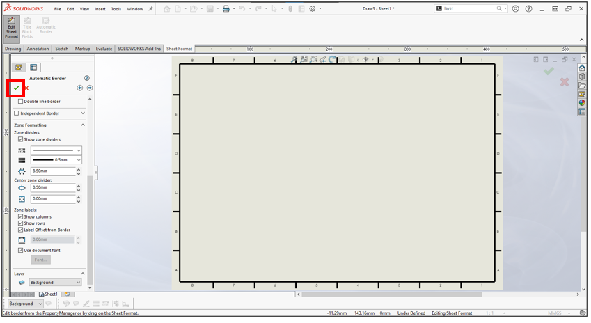 9. The “Zone Formatting” is optional. Click “OK” if you finish the setting.
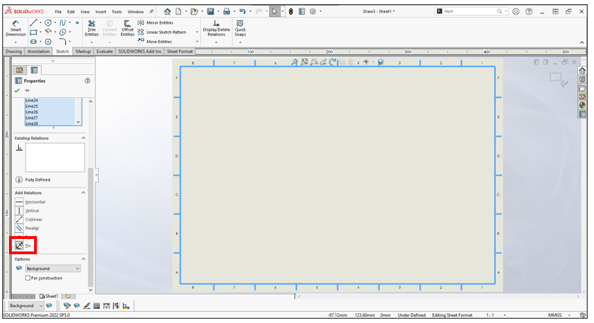
10. Press keyboard “Ctrl” & “A” to select all lines and add a “Fix” relation.
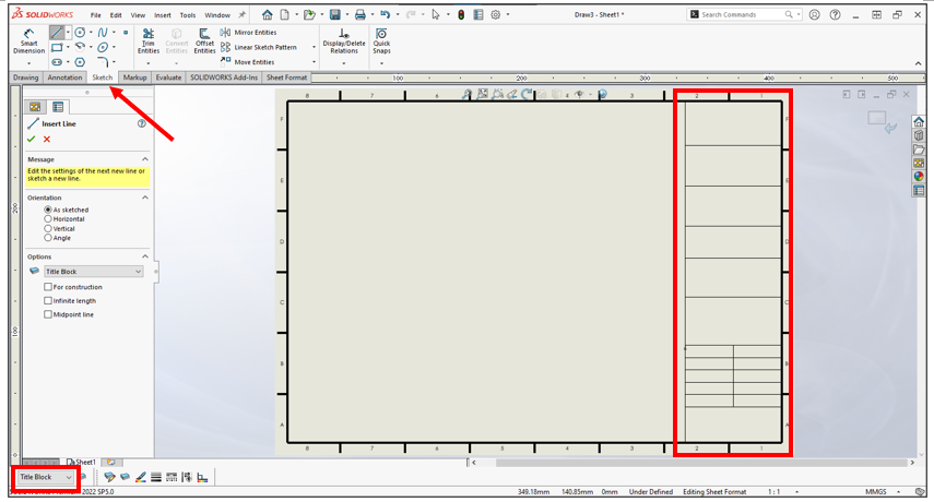
11. Set the “Title Block” as a current layer. Start sketching the boxes shown above.
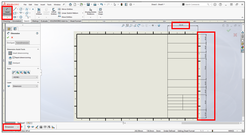
12. Set the “Dimension” as a current layer. Use “Smart Dimension” to define the size of the boxes. It is not necessary to make it be “Fully Defined”.
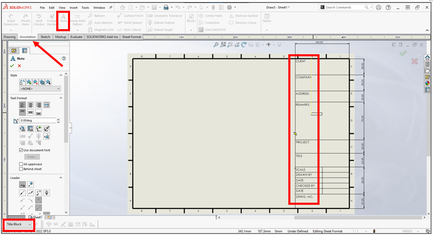
13. Set the “Title Block” as a current layer. Click “Note” at “Annotation” tab to write the text shown above.
14. Open the “Layer Properties” and hide the “Dimension” layer. Click “OK”.
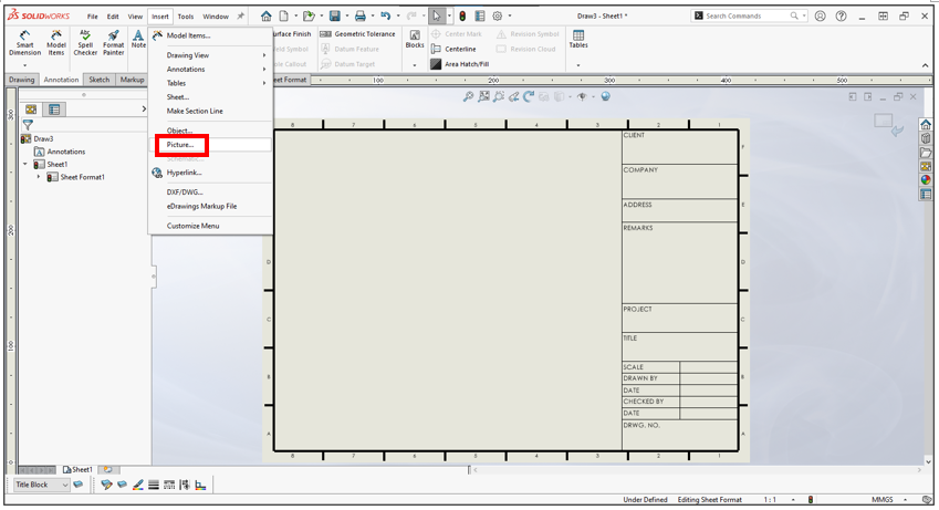
15. Click “Insert” > “Picture…” to insert a picture from the computer.
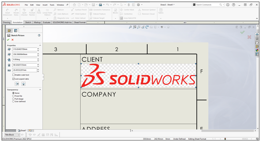
16. Resize and drag the picture to correct location.
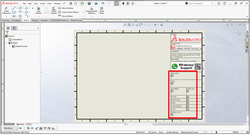
17. Click “Note” at “Annotation” tab to add the empty notes shown above.
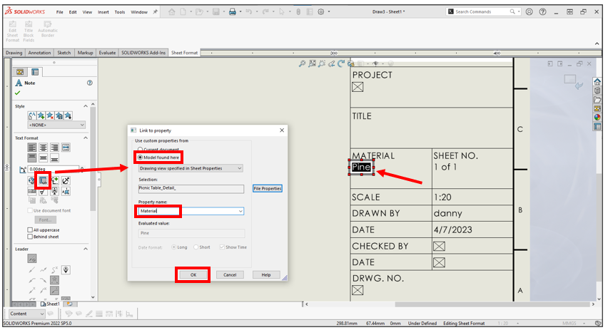
18. Double-click the box. Click “Link to property”. Click “Model found here”. Select “Material”. Click “OK”.
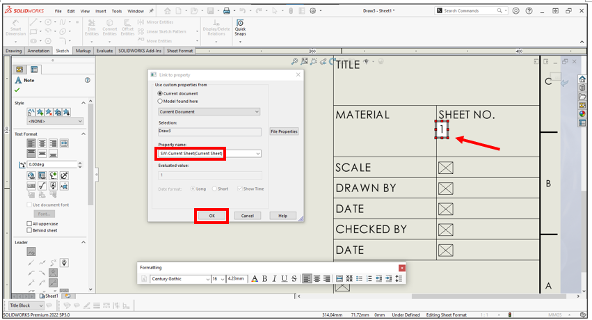
19. Select “SW-Current Sheet(Current Sheet)”.
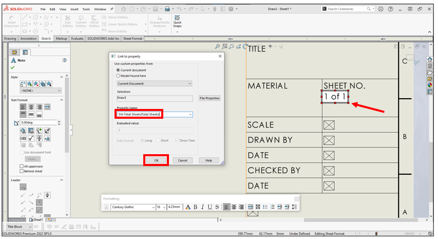
20. Write “ of “ and click “Link to property” again. Select “SW-Total Sheets(Total Sheets)”.
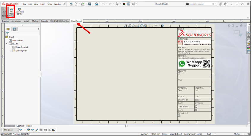
21. Click “Title Block Fields” at “Sheet Format” tab.
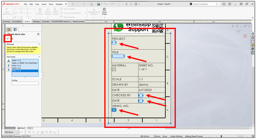
22. Resize drag the box to correct location shown above. Select the “Note” that you want to write the text manually. Click “OK”.
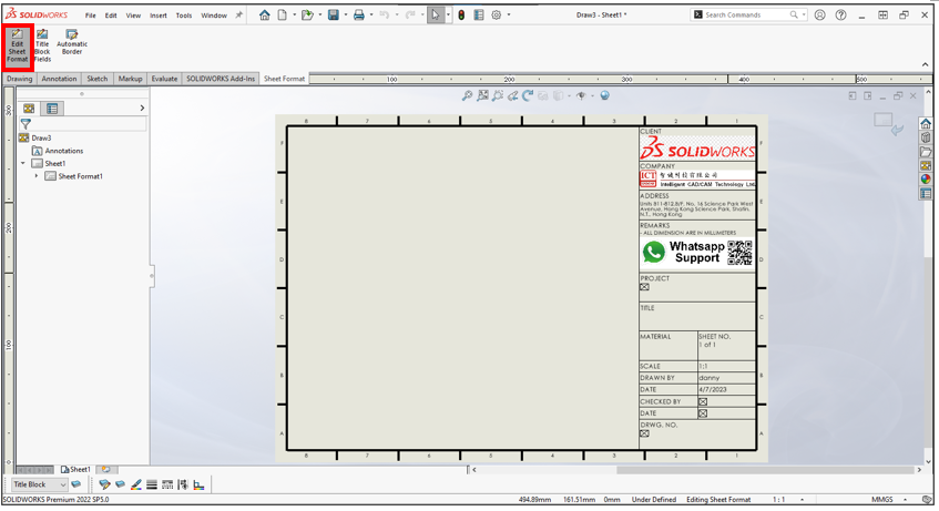
23. Click “Edit Sheet Format”.
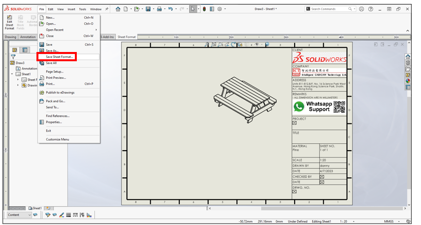
24. Set the “Content” as a current layer. Click “file” > “Save Sheet Format…”.
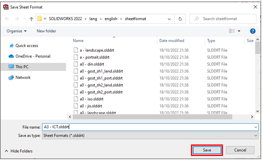
25. Rename it and click “Save”. You can save it to another location to make a backup.
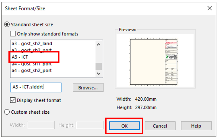
Select the new drawing template from the list. Click “OK”.
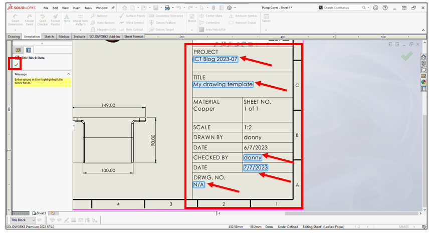
Double-click the “Title Block Fields” box to input the text shown above. Click “OK” to exit.
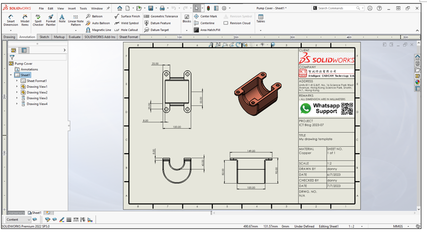
Finish.
In this blog, we just highlight the major information. Please see the PDF of the complete step attached if you are interested. You can apply these methods to your other specific setting.
Written by Danny Cheung, Intelligent CAD/CAM Technology Ltd.